Change Global Sheet Metal Thickness Solidworks

Solidworks 2019 Link Sheet Metal Parameters To Specific Material Youtube
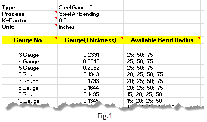
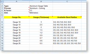
What Sheet Metal Gauge Tables Does Solidworks Provide With Its Installation
Sheet Metal Success In Solidworks Engineers Rule
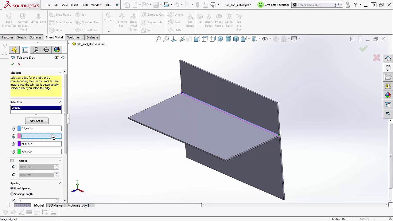
Solidworks 2018 Sheetmetal Tab And Slot Youtube

Spotlight On Features Sheet Metal And Gauge Table Rules Part I
Solidworks 2017 Sheet Metal Options
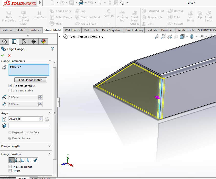
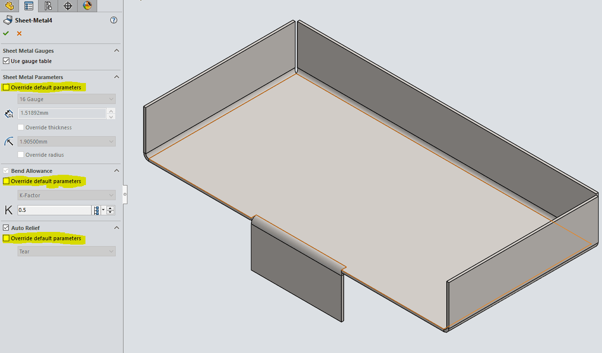
If you want a body to have a different thickness from the part thickness you edit the sheet metal body feature check the override default parameters and enter the desired thickness fig.
Change global sheet metal thickness solidworks.
How To Drive Sheet Metal Parts Kb12121018 Driveworks Documentation

Solidworks 2019 Office 365 Excel Design Table Problem Solidworks Table Design Design

Spotlight On Features Working With Sheet Metal Tables Understanding The Measured Parameters

How To Convert Thickness Into A Solidworks Sheet Metal Gauge Value
Source : pinterest.com
